Rudders/Elevators
Rubber and Elevator Surfaces
Nearly all the rudders and elevators were constructed of balsa sheets
sanded
to some airfoil shape. The thicknesses varied from 1/8" to
1/4", permitting different airfoil shapes. Elevator
were covered with light glass or just sealed with dope and hinged.
The rudder and elevators of the Photons and the Watson Sidewinder were
made of spyder foam covered with 0.75 oz. fiberglass. There were
many approaches to shapes and weights. Most planes had tail
surfaces with low surface area. This was to reduce the weight
out on the long tail moments, permitting less weight to be required in
the nose beyond the weight of the batteries, receiver and
servos. The small control surfaces created problems with the
airplane controls during the launch. To compensate, many pilots
used the high tech solution of the contest, that is, they installed a
gyro. If the surfaces are larger, and the plane designed
properly, the gyros is not needed. (At this point it might have
a placebo effect.)
Three designers, Bill Watson, Jerry Krainock, and
Larry Pettyjohn, used spyder foam covered with fiberglass in their
tails. These were much stronger and lighter than balsa tails for
their size.
Configurations:
The type of tail used on the hand launched gliders differ
significantly as compared to a thermal duration class ship.
There several general trends. This is an area of controversy,
and the general considerations are presented here.
Conventional Tails
Originally, planes with T-tails and rudders attached at their midpoint
were used by discus launched planes. Examples of these are seen
in the Uplink by Dick Barker, who was one of the first proponents of the
discus launching style. As explained to this designer, the theory
is interesting. Taking a regular tail group with the elevator at
the base of the rudder and the fuselage (or tailboom) attached to the
rudder at it's base, one needs to look at the deflection on the rudder
when right rudder is applied. At the time of launch, the wing is
not responding to the forces imposed upon it by the tail. As
such, the rudder acts as a propeller with respect to the
fuselage. This action forces the fuselage to rotate left.
At the same time, the outboard wing of the glider is traveling faster
and creating greater lift than the inboard wing. This compounds
the effect of the rotation causing the plane to go into a left roll
when launched. It is only when the rudder becomes effective with
the wing that the right rudder offset rolls the plane to the right. To
counter some of these forces subrudders are used.
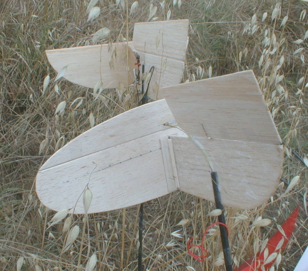
Sub-Rudders:
Reviewing the presentation above, if the tailboom is attached to the
midspan of the rudder, the rotating forces are changed. Viewing
the rudder form behind, with right rudder applied, the viewer can see
that the rudder above the tailboom wants to rotate the plane to the
left. Looking at the portion of the rudder below the tailboom,
the right rudder lower portion wants to rotate the fuselage in the opposite
direction. This effectively counterbalances the forces applied
by the upper portion of the rudder. The designer is now faced
only with the rolling induced by the differential of wingtip
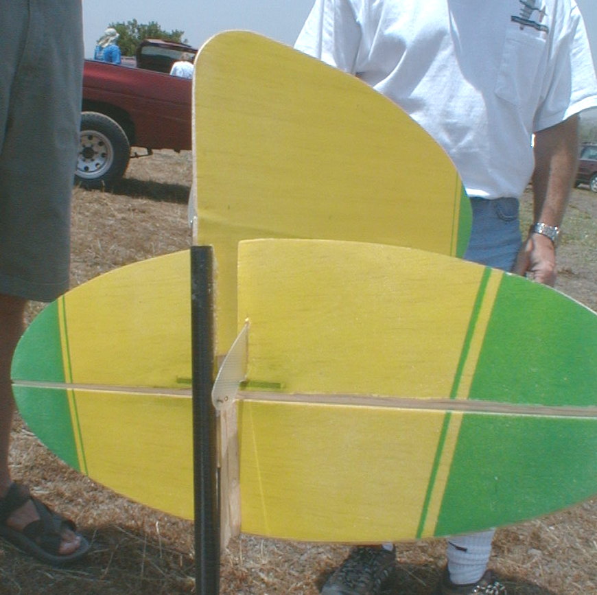
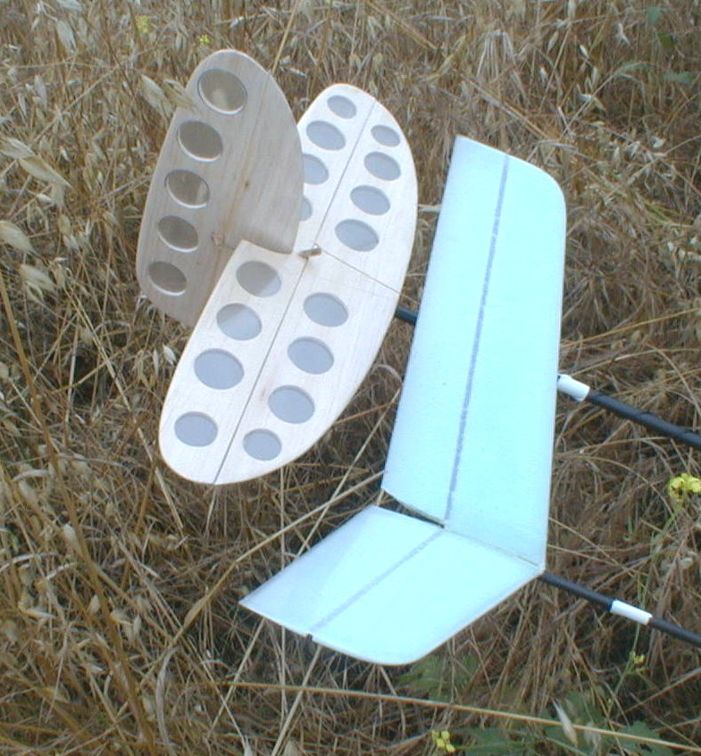
speed. Nowell Segal took the subrudder to an extreme with his
design, which uses the same planform for both the rudder and the elevator.
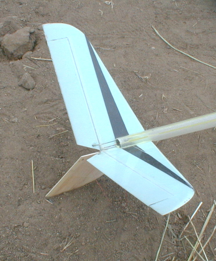
T-Tails
T-tails provide some advantages. First of all, the
T-tail is a more efficient design, hence the plane has better performance.
The T-tail permits easy removal of the tailplane for shipping.
The T-tail also permits direct solid control linkage connection.
The only drawbacks to using a T-tasil are the rigidity
of the tailboom, the moments of the T-tail, and any induced rolling
behavior induced by the elevator.
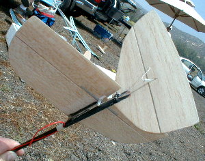
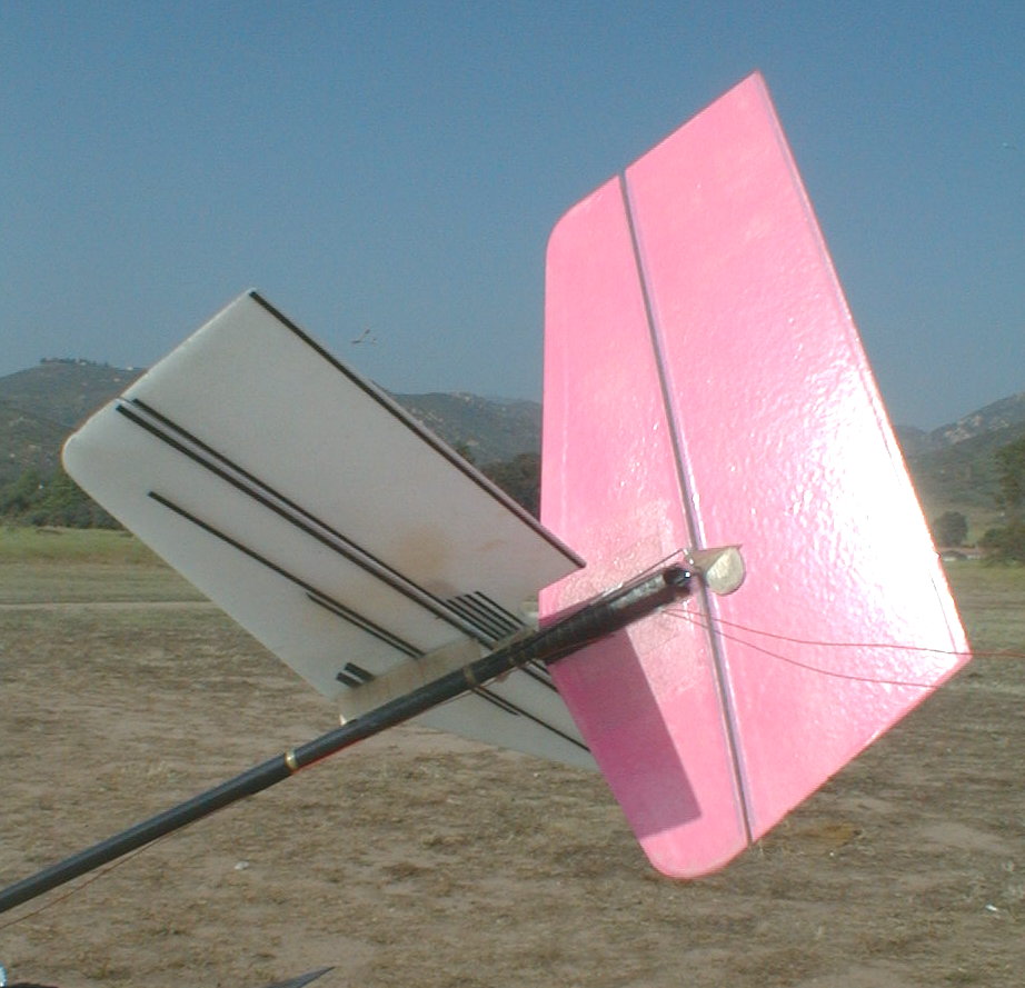
V-Tails
V-tails offer a more complicated analysis, which is among the
most interesting discussions used by those who like V-tail
designs. One perceived advantage of a V-tail is that of one less
flying surface. With one less surface, a large portion of the
tails weight is reduced. Often the V-Tail is a bit larger.
However, if a discussion is provided where the V-tail surfaces are
deflected to roll the plane to the right following the launch, you can
see that both surfaces want to rotate the fuselage to the left.
At speed, the V-tail takes over and rotates the plane to the
right. There was only one plane that used a V-tail on a flexible
carbon tailbooms. The Texas Twister uses a much stiffer
fiberglass tailboom, a tailboom of a larger diameter, to stop the
deflection and twisting induced by the surfaces.
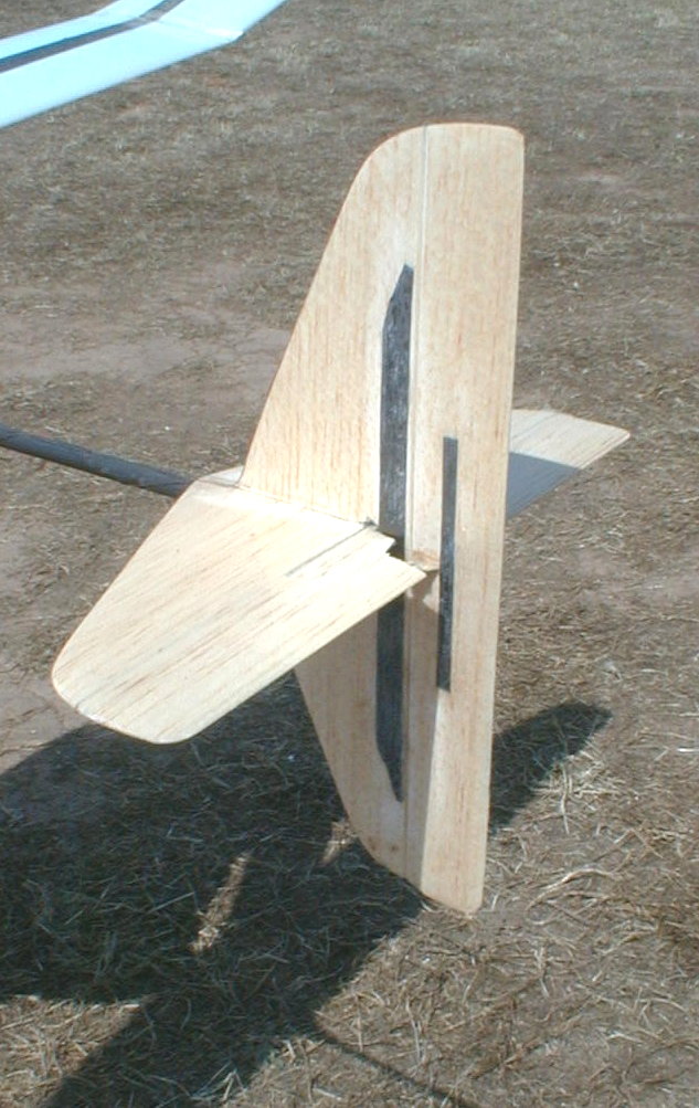
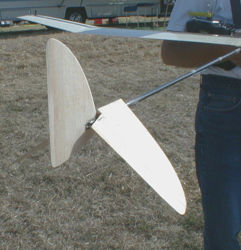
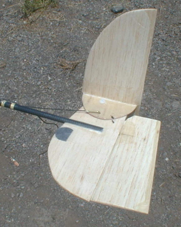
SubRudders on Conventional Tails
A compromise to all the discussions above is the use of offset
conventional tails. By offset, it is meant that the elevator is
generally in front of the rudder and mounted just above the tailboom.
By using a subrudder the twisting of the tailboom is reduced.
This permits the rudder to address it's action to countering the roll
of the wing. By placing the rudder farther back from the wing,
greater roll stability is given to the plane.
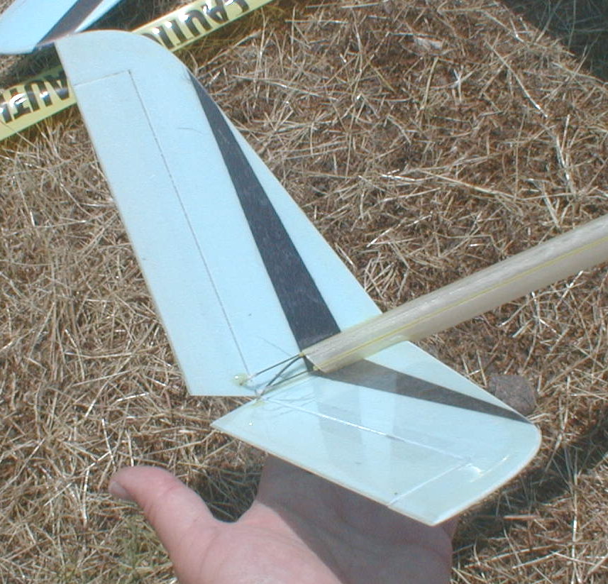
Having the elevator in front of the rudder, the designer retains the
response of the plane to up and down. The elevator can be used
to keep the plane in a tight turn. With the elevator mounted
above the tailboom, the control horns do not project below the
tailboom and the pushrods do not have to be bent to meet the control
horn. Mounting the elevator above the tailboom permits the elevator
to be removed easily for shipping. Removable elevators mount on
and are stabilized by a T-shaped support surface. This mounting technique
also permits fine tuning of the angle of
attack of the elevator with respect to the wing.
All moving Elevators/Stabilators
In theory, elevators with articulated surfaces, that is elevators with
a fixed front
portion and a moving rear portion do
not stall as rapidly as fully moveable stabilators. Often polars are
provided for both these designs. Also, with articulated
surfaces, the angle of attack changes more rapidly with control
surface deflection. Thus, with lower deflection, greater force on
the wing is produced and less drag by the surface is realized.
The theorists can address this further. However, for those
planes with all moving surfaces, the pilot can place the tailplane at
the proper angle for flight control. The Goblin and Ionosphere
by Thermal-Gromit Works use all moving tailplanes in their
designs.
V-Tails with Subrudders:
One designer added a subrudder to the V-tail. This
was an attempt to
improve the stability and responsiveness of the plane.
Controls:
The controls for the rudder and elevator
flight surfaces showed a lot of diversification and thought. The
mechanisms of control varied as follows:
1) Pushrods;
2) Pull-Pull using threads or cords; and
3) Pull-Pull loops using threads or cords.
Each method attempted to reduce control surface play, and
to increase plane response to the surface movements. At the
center of these controls is the ease with which the linkages are
maintained and adjusted, as well as the durability and weight.
Let's look at each of these individually.
Pushrods
Pushrods, originally wires within a sleeve, are heavy. Weight is
a real problem when the tail moments are increased. As the
weight out toward the tail increases, more noseweight must be
added. Hence, carbon fiber pushrods are substituted for the
wires. The most common carbon fiber rods are 0.035" in
diameter.
Most planes have the carbon fiber rods within the
tapered tailbooms, exiting near the tail. One major problem is
the play within the tailboom, as the carbon fiber rods can bend
slightly within the boom. Many users shroud the rod with a
sleeve, and the sleeve is secured within the tailboom to reduce slop and
linkage play. This is somewhat acceptable for low diameter
tailbooms; however, it is unacceptable for large tailbooms.
This issue was solved by Bill Watson with his Sidewinder, who encases
his carbon fiber rods in a teflon tube and the teflon tube is held or
glued in place along the outside of the tailboom.
Alternatively, the carbon fiber rods are removed
entirely through the use of a pull-pull cord
mechanism.
Pull-Pull using Threads and Cords
The simplest of all control linkages to the rudder or elevator
surfaces had control horns on either side of the moveable surface.
The
cords, made of spectra fishing line, are threaded through openings in
the tailboom, inside the tailboom and then connected to the control
horn on the servo. For adjustment, the cords are threaded
through the outer holes in the control arm and then fixed in place,
either using the screw holding the servo arm to the servo, or fixed to
another portion of the servo arm.
There are advantages and disadvantages to this
system. The advantage is that solid control of the surface is
possible, however care must be taken as to not over-tighten the
linkages. This can cause stress on the control horns.
Additionally, if the cords are tight, any flexing of the tailboom can
increase the tension on one cord, or the other, potentially loosening
the linkage or over-stressing the linkage. This stress may
damage the surface and it's movement.
Pull-Pull Loops using Thread and Cords
To eliminate the stresses on the control surfaces, a loop system can be
used. Basically it is just like the pull-pull setup, but differs
in that the cords are looped around a point at the end of the tailboom.
This method is most commonly used with elevators. With a close
loop system, the connection to the elevator can be anywhere along the
length of the loop, but is generally at one end. For example, only
one control horn is required on the elevator surface. Pulling
toward the front of the plane by one thread, give down elevator.
Pulling the other cord as it loops around the turn point at the end of
the tailboom, pulls the control horn back, giving up elevator. The
advantage here is that the elevator does not see the stresses induced by
the dual control horn connections.
Which is the easiest to use? View the examples below to see how each
is configured.
For additional photos click here: Additional
R/E photos 1
|