International Hand Launch Glider Festival June 3-4, 2001
| Fuselages |
Mounting of the radio system containing the receiver, batteries and servos is often a tight fit. There are several issues which must be addressed when the radio components are being mounted in the fuselage. 1) There must be easy access to the on/off switch. Whether it be a switch accessed by a slip on nosecone, or perhaps an earphone jack, the user must have a dependable on/off switch. In the case of the earphone jack, the jack can double as a connection to the battery for the charging of the batteries between flights or rounds. 2) The components must be placed as far forward as possible in order to reduce the amount of lead needed (if required) to balance the plane at the CG. 3) The pilot must be able to adjust the control linkages, especially if the pull-pull mechanism lines become slack or loose. 4) Sufficient batteries must be used in order to span the duration of the flight round. For the new 4 and 6 servo planes, these batteries must last for at least 10 minutes. The idle current for the receiver and servos is low when the servos are not moving. When more servos are used, or when the servos are constantly moving, the servos have larger current demands. Larger capacity batteries are required to meet the current drain requirements. Pilots have been going to larger capacity NiCad batteries or to Nickel Metal Hydride (NiMH) batteries. For the same size as NiCads, NiMH batteries offer 4-5 times the capacity. The user should be aware of the limitations which the NiMH batteries might have. The main limitation is the ability to discharge current during high current drain times. Some NiMH batteries cannot handle the current drain, as the voltage of the battery pack may go below the required voltage for proper receiver operation. In other words, the pilot may see glitches under high current drain conditions. The user should check to be sure the voltage drop is not present. 5) For fly off rounds, the pilot may be required to change their frequency in order to provide the ability of man-on-man elimination rounds. As a pilot, the ability to change crystals is very important. It must be easily and quickly accessed, without changing any control connections or the plane's CG. 6) While a contestant may not want to dissect a plane during the contest, the pilot must be aware that a servo may strip a gear during the heat of a contest, or following a rough landing. 7) The fuselage must be able to withstand the hard discus throws. Both the wing mounting pins and the forward part of the fuselage, must be able to handle the side forces of the launch.
|
|
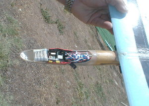
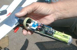
This is a view of the radio installation of Darwin Barrie's Raptor. Darwin is using 2 HS-55s driving pull-pull connections to the rudder and elevator. In the front is a 4 cell NiH pack derived from a 9 volt NiMH transistor radio battery from Radio Shack. The pack weighs approximately 0.8 oz. and has a rated capacity of 150 mAh. The receiver is a Hitec 555. The switch is a simple plug in direct connection to the receiver of the battery pack connector. |
|
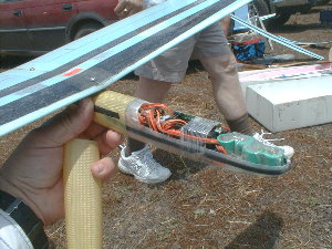
This is a view of the radio installation of Joe Wurts in his 6 servo Raptor. The green batteries in front are 350 mAh NiMH cells. Although weighing a bit more, the philosophy to use battery weight to replace any lead weight used for balancing, provides more security to the pilot. The pilot knows that he will have sufficient flight time power, so it may not be necessary to charge the plane between rounds. Here Joe is using a IPD receiver and HS-55 servos. |
|
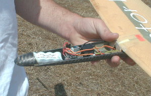
This is the radio installation in Craig Greening's XTerminator Pro. The CF fuselage has a flatter profile, permitting easy installation of the battery, receiver and servos. Here the servos are laid on their side with the control arms pointing up. |
|
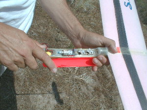
This is the radio installation for Chris Oster's Texas Twister. The fuselage is molded with a flat tray opening and slip on nosecone. Having a cutout for the fuselage adds strength to the nose, however it does add some difficulty with accessing the radio gear. The example shown here is representative of many HLG fuselages. |
|
This is the radio installation of the Sidewinder by John Petriek. John is using JR 241 servos along with a 555 receiver |
|
This is the radio installation of Bill Watson. Bill took a lot of time in designing the radio installation to fit nearly all the needs of the pilot and plane. The fuselage is molded with carbon fiber pre-preg cloth cured at high temperature. Once the fuselage is cured, the front part of the fuse is cut apart. The inside of the forward part of the fuselage is reinforced with glass cloth and finished smooth. The inside is then waxed and PVA added. The nosecone is then retaped in place, and from the wing saddle access a layer of fiberglass is placed over the seam inside. Once cured the nosecone is removed, leaving a nosecone lip, shown by Bill's thumb. This is finished smooth. To mount the radio, rails of a sandwich of carbon-balsa-carbon is made and glued to the inside of the fuselage. The width fits the HS-55 servos, receiver and batteries. The servo leads are shortened to reduce weight. This permits easy access to the servos, which do not have to be removed in order to change gears, if required, as well as the ability to turn the radio on and switch crystals. |